MPO vs MTP Connectors: Key Differences, Compatibility & Best Use Cases
- February 7, 2026
- fiber optic cabling
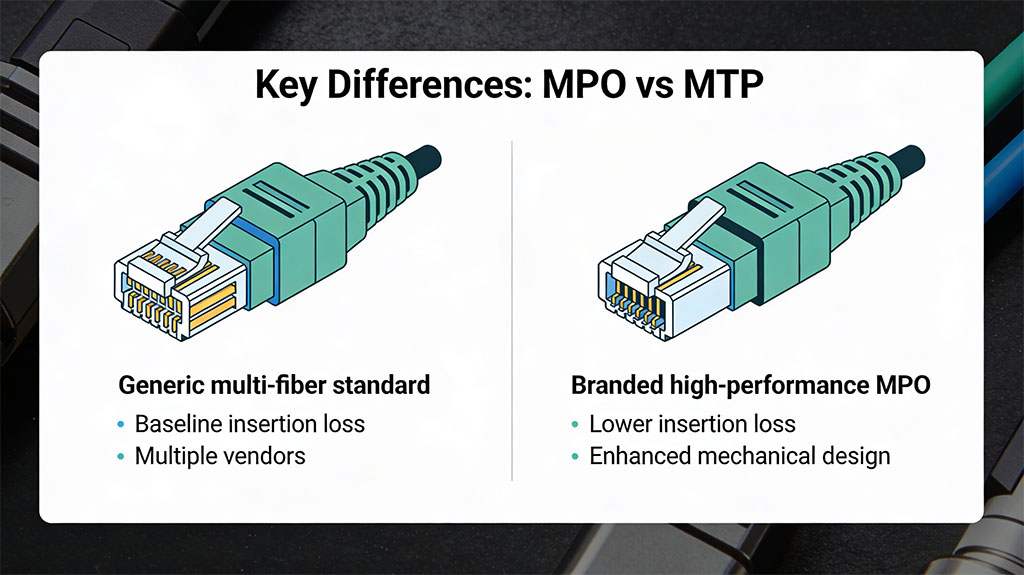
MPO and MTP are closely related multi‑fiber connectors, but MTP is a higher‑performance, branded version of the standard MPO.
Quick overview: MPO vs MTP
- MPO (Multi‑Fiber Push‑On) is an IEC/TIA standardized multi‑fiber connector type used for high‑density fiber cabling (e.g., 8, 12, 24+ fibers in one ferrule).
- MTP® is US Conec’s trademarked, enhanced MPO connector with tighter mechanical tolerances and lower loss, fully compliant and interoperable with standard MPO.
- All MTP connectors are MPO‑type connectors, but not all MPO connectors are MTP.
What is an MPO connector?
- MPO stands for “Multi‑Fiber Push‑On,” a multi‑fiber array connector defined by IEC 61754‑7 and TIA‑604‑5 (FOCIS‑5).
- It uses a rectangular MT ferrule (about 6.4 mm × 2.5 mm) that can hold multiple fibers (commonly 8, 12, 16, 24, and higher counts).
- MPO connectors can be male (with guide pins) or female (with guide pin holes) and use a push‑pull latch for quick mating in panels and cassettes.
- They are widely used in data centers to support 40G, 100G and higher‑speed parallel optics because they deliver very high fiber density in limited rack space.
What is an MTP connector?
- MTP is a registered trademark of US Conec for a high‑performance MPO‑format connector (MTP = Multifiber Termination Push‑on).
- MTP connectors are fully compliant with MPO intermateability standards (IEC 61754‑7, TIA‑604‑5), so they can plug into standard MPO adapters and components.
- US Conec engineers the MTP ferrule, housing, and internal parts to exceed the baseline MPO requirements, targeting lower insertion loss and higher reliability.
- Optimized MT ferrules for tighter fiber alignment.
- Improved end‑face geometry for lower insertion and return loss.
- Enhanced latching and boot designs to reduce debris and mechanical stress.
- Variants like MTP PRO that allow field pin and polarity changes.
Key differences: MPO vs MTP
1. Standard vs brand
- MPO is the generic connector family defined by international and North American standards.
- MTP is a branded, premium implementation of the MPO design from one manufacturer (US Conec).
2. Mechanical design enhancements
MTP introduces several mechanical upgrades compared to a typical MPO:
- Ferrule precision: MTP ferrules use higher‑precision molding and tighter tolerances for fiber hole position and diameter, improving core‑to‑core alignment.
- Spring design: MTP uses an oval spring that spreads contact force more evenly and reduces stress on ribbon fibers, whereas many MPOs use a round spring.
- Guide pin tips: MTP uses patented elliptical pin tips to minimize wear on guide pin holes; many MPOs use chamfered pins with sharper edges that can cause more wear.
- Floating ferrule: Some MTP designs use a floating ferrule that can move slightly to maintain better physical contact under load or thermal variation, improving mechanical stability.
These design changes help maintain consistent contact between fiber end faces, which directly supports lower loss and longer connector life in high‑density environments.
3. Optical performance (loss)
- Generic MPO connectors are typically qualified to meet baseline insertion and return loss values defined by standards.
- MTP connectors are engineered to deliver significantly lower insertion loss and better return loss, and MTP “elite” variants can rival or outperform many single‑fiber connectors from a few years ago.
For example, some manufacturers specify maximum insertion loss around 0.6 dB for multimode MTP connectors, lower than many generic MPO equivalents, which is critical when links include several connector pairs.
4. Reliability and longevity
- High‑density data center links are mated and unmated many times, so wear on guide pin holes, ferrule end faces, and latching mechanisms matters.
- MTP’s elliptical guide pins, optimized latch, and robust boot are designed to reduce wear, keep debris out, and maintain stable contact pressure over many mating cycles.
- In practice, this means fewer random failures, fewer intermittent errors from micro‑movement, and better long‑term stability in critical links.
Compatibility and intermateability
- Any compliant MPO and MTP connector share the same external footprint and adapter interface, so they can physically plug into each other.
- Intermateability depends on two things: following IEC 61754‑7/TIA‑604‑5 dimensions and matching polarity/fiber mapping.
- It is common to see structured cabling that uses MTP trunks with MPO cassettes or vice versa, as long as loss budgets and performance needs are respected.
A key point: an MTP connector is designed to be backward compatible with generic MPO infrastructures, but a generic MPO may not deliver the same performance when plugged into a link engineered around low‑loss MTP components.
When to choose MPO vs MTP
Choose generic MPO when:
- Budget is tight and links are short with few connector pairs.
- The application is less demanding (e.g., some enterprise backbones, moderate‑density patching) where slightly higher loss is acceptable.
Choose MTP when:
- You are designing high‑speed (40G/100G/400G) or long‑reach links where every fraction of a dB in loss matters.
- The link uses multiple connector pairs (trunks, cassettes, patch leads), making low‑loss components essential to stay within budget.
- You need high reliability and frequent re‑patching in dense data centers and colocation facilities.
- You want advanced features like field‑reconfigurable polarity and pins offered by MTP PRO.
A simple rule of thumb: for modern data centers and AI/10G+/40G+/100G+ ready infrastructure, investing in MTP components usually pays off in easier design, better margins, and fewer troubleshooting headaches, while generic MPO can still be fine for shorter, less critical runs where cost is the priority.
MPO vs MTP compatibility with LC connectors
MPO and MTP do not plug directly into LC ports, but both are fully compatible with LC connectors through breakout/harness cables and cassettes that convert one multi‑fiber MPO/MTP into multiple LC duplex ports.
How MPO/MTP connect to LC
- MPO and MTP use a multi‑fiber MT ferrule, while LC is a single‑fiber duplex connector, so you need a transition component between them.
- That transition is usually a breakout/harness cable (MPO/MTP on one end, multiple LCs on the other) or an MPO/MTP cassette with an LC front panel.
Example: an 8‑fiber MTP/MPO–LC harness takes a 40G QSFP port (MPO/MTP) and breaks it into four 10G LC duplex links to SFP+ ports.
MPO vs MTP with LC: what’s different?
- From the LC side, there is no difference: LC connectors mate the same way whether the trunk is generic MPO or branded MTP.
- The MPO/MTP side differs in performance and mechanics only; MTP is a higher‑precision MPO, but both can be terminated to LC fan‑outs or LC cassettes.
So “MPO‑LC breakout” and “MTP‑LC breakout” are functionally the same concept; vendors often even label them “MTP/MPO‑LC harness cables.”
Typical MPO/MTP–LC options
- 8‑fiber: 1 × MPO/MTP to 4 × LC duplex (e.g., 40G QSFP to 4 × 10G SFP+).
- 12‑fiber: 1 × MPO/MTP to 6 × LC duplex (e.g., 6 × 10G).
- 24‑fiber and higher: 1 × MPO/MTP to 12+ LC duplex for dense patching.
These assemblies are available in OS2, OM3, OM4, etc., with different loss grades, and are commonly used for high‑density data center interconnects.
Compatibility rules to watch
- Polarity and mapping: Make sure the MPO/MTP polarity type (A/B/C) and fiber mapping match the transceiver and panel design, otherwise LC channels will be mis‑routed.
- Gender: QSFP/QSFP28 ports are usually male MPO/MTP, so your MPO/MTP–LC breakout must present a female connector to them.
- Loss budget: Low‑loss MTP trunks plus quality LC connectors are safer for multi‑connector paths at 40/100G+; generic higher‑loss MPO plus several LC pairs can easily blow the budget.
In practice: choose MTP‑LC harnesses for premium, low‑loss, high‑density data center links, and MPO‑LC harnesses for shorter or less critical runs where cost is more important than squeezing every fraction of a dB.
What polarity types are needed for MPO LC breakout cables
For MPO‑LC breakout cables, you typically use Type A or Type B polarity (not Type C), and the “right” choice depends on how the whole channel (transceiver → trunk → cassette/patch panel → LC equipment) is designed.
The three MPO polarity types (quick recap)
- Type A (straight‑through): Pin 1 → Pin 1, Pin 2 → Pin 2, etc.; usually key‑up to key‑down; used as a simple trunk extension where endpoint hardware or cassettes handle any flips.
- Type B (reversed): Pin 1 → Pin 12, Pin 2 → Pin 11, etc.; usually key‑up to key‑up; provides a full end‑to‑end flip (Tx ↔ Rx) and is common for direct 40/100G SR4 links.
- Type C (pairwise‑flipped): Adjacent pairs crossed inside the cable (1↔2, 3↔4…); mainly used in some duplex LC patching architectures, not typical for QSFP→LC breakouts.
What polarity is used for MPO‑LC breakouts?
In practice, MPO‑LC breakouts are built as either Type A or Type B harnesses; vendors rarely offer Type C for this.
- Many QSFP→LC harnesses (e.g., 40G/100G to 4×10G/4×25G) are Type B so that QSFP Tx pins map correctly to LC Rx ports at the far end.
- Some breakout panels/cassettes and LGX modules specify Type A (1‑1) MPO to LC wiring, relying on system‑level Method A polarity (cassette + duplex LC patch cords) to maintain Tx→Rx paths.
So the polarity you “need” is whatever matches the polarity method of the overall link (Method A or Method B), not an absolute rule for LC breakouts themselves.
Practical guidance by use case
- QSFP/QSFP28/QSFP56 40G/100G/200G → multiple 10G/25G LC ports
- MPO trunk to an LC breakout panel or cassette
- If your trunks and cassettes follow Method A, your LC breakout cassette or panel is typically Type A (1‑1) inside, and the “flip” is handled by the duplex LC patch leads and cassette design.
- If your infrastructure is built around Method B, you’ll usually use Type B MPO trunks and Type B cassettes/breakouts so the overall channel still delivers Tx→Rx correctly.
How to choose for a real deployment
- Confirm the polarity method your vendor or design (Method A, B, or C) is using in the MPO backbone.
- Check your transceiver pinouts (e.g., QSFP SR4 pins for Tx/Rx) and your panel/cassette documentation; manufacturers usually state “Type A” or “Type B” for their MPO‑LC modules or harnesses.
- Match the breakout cable polarity to that design; never mix Type A and Type B randomly, or your LC ports will have Tx talking to Tx and Rx to Rx.
For most data‑center style QSFP→LC breakouts, starting with Type B MPO‑LC harnesses is a safe default, but for structured cabling with trunks and cassettes you should align with the chosen polarity method (often Method A with Type A trunks and Type A breakout panels).
Fiber-Cabling.com
is Toronto’s top fiber optic design and installation provider, serving clients across Canada. We specialize in fiber layout design, supply, splicing, and testing, ensuring reliable, future-ready connectivity. With expert installations and quality materials, we deliver top-tier fiber solutions tailored to your needs. Contact us for a free consultation today!
Request a free quote
Looking to enhance your network with top-tier fiber optic solutions? Get in touch with Fiber-Cabling.com for a free consultation. Our team is ready to assist you with all your fiber optic needs, from design and installation to testing and maintenance.
Subscribe to our newsletter!
More from our blog
See all posts